Bucket Elevator lift belt
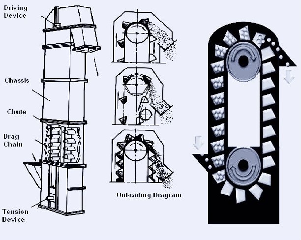
The Bucket Elevator lift belt positioned at the top of the self unloading bulk carriers cargo transfer system to assist in emptying of cargo from pockets.The lift belts are housed inside the lift belt casing, which is located just forward of the accommodation block.
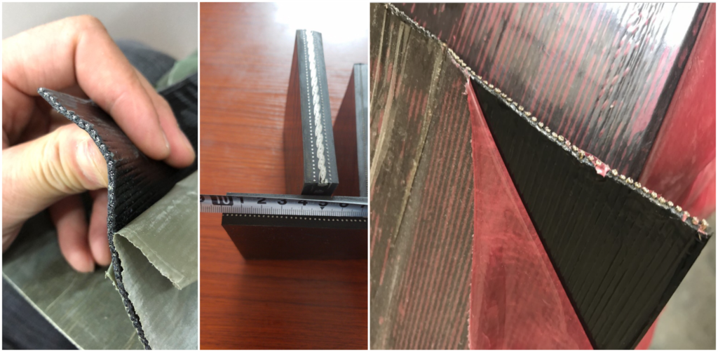
The lift belt is reinforced with steel cables running longitudinally throughout its entire length. Corrugated side walls are attached, also running longitudinally for the entire length. Pockets are formed by rubber “cleats” which are bolted onto the belt, using side bars, through the side walls. The cleats are secured to intermediate blocks of rubber, and inside each are embedded stainless steel “U” bolts whose ends protrude from the rubber. Each block is attached to the belt by a cold adhesive process. The cleats are secured to the “U” bolts using stainless steel cap nuts.

The Bucket Elevator lift belt therefore has pockets on its carrying side and is smooth on the other. The lagged pulley drives on the smooth side of the belt, and there is no hydraulic take-up arrangement. Belt tension is set by the tail pulley position using jacking screws.

The tension of this type of belt is not to be adjusted by ship staff. It is only to be adjusted by “flexowell” approved technicians.
The belt is driven by two Hagglunds hydraulic motors which are attached to each end of the drive pulley shaft located at the top of the lift belt casing. The ratchet type backstops are located adjacent to the drive motors and are attached to the upper aft deflection wheel shaft of each belt, which allows the belt to rotate in one direction only. Any change of direction of this belt is effected by ‘deflection wheels’ which are on the carrying side edges of the belt when change of direction is desired. The loading of this belt is transferred via chutes on the carrying pocket side at the bottom just aft of the take-up pulley. The underside of the belt, along its loading area is supported by load rollers, which are rubber lagged to absorb the impact of the cargo.

The advantages of the Lift Belt System are:
- It occupies less space in the vessel than any other elevator belt system, as the angle of the elevation is vertical.
- It requires a smaller number of rollers to support the belt.
The disadvantages of the Lift Belt System are:
- High Cost
- Long belt change-out time required i.e. three to four weeks and this can only be performed in a shipyard with sufficient crane height, and capacity.
- The belts are prone to damage from cargo falling from the upper part of the system.
- The belts are prone to damage if the side guide wheels become
- seized. The resultant edge damage lays open the steel cables to corrosion which will eventually result in the belt being scrapped.Important note: the side guide wheels must be inspected during and after each discharge. Any seized guide wheels must be repaired immediately. Any edge damages on the lift belt must be repaired using cold cure procedures immediately.
- Hotwork in the lift belt casing is extremely hazardous as hot material can lodge in the pockets.
- Lift belts are susceptible to stalling, if the system is shut down during high rates of discharge.
The loop belt elevator
The loop-belt arrangement is housed in the ‘Loop-Belt Casing’ of the self unloading bulk carriers cargo transfer system and found normally just in front of the ships bridgefront bulkhead. The loop belt elevates cargo material using two belts arranged in a ‘C’ form, with one driven outer belt, and one non-driven inner belt. These belts turn on “trough” section rollers the outer edges of which contain the cargo material within the belts.
The cargo material is lifted in the sandwich formed between the two belts the tension of which creates the clamping force and resultant friction necessary to lift the material.
The system is driven by electric motors at each end of the outer belt using fluid couplings and reduction gearboxes. Speed sensing ensures that the speed of the inner belt which is driven by the friction between the two belts, does not fall below a pre-set level. This is to avoid a reduction in the transfer of cargo material and resultant build up of cargo material at the bottom of the loop elevator. If slippage does occur to the extent that the pre-set level is exceeded then the tunnel and transfer belts will automatically stop.
In the event of a stoppage, the loop belt system is prevented from running backwards under the forces of gravity, by two backstops fitted inside each reduction gearbox.
The hydraulic tensioning of the loop belt system is critical, and the design specifications must be complied with.
The advantages of a Loop Belt Elevating System are as follows:
- High cargo handling capacity
- A relatively small volume of the vessel is occupied by the Loop System with its near vertical lift.
- Belts can be completely changed out in a short period of time i.e. three to five days.
- Easy to maintain.
- Belting material is available from several manufacturers at competitive prices.
- Simple and robust drive system.
- A minimum of automation is required.

